
Interactive 3D experience
Rotate, zoom, isolate vehicle systems and explore an exploded assembly in the browser.
Explore a generic vehicle through interactive 3D visualization, automotive system architecture and engineering-grade CAD workflows. Move from the complete vehicle to assemblies, components, materials and manufacturing processes.
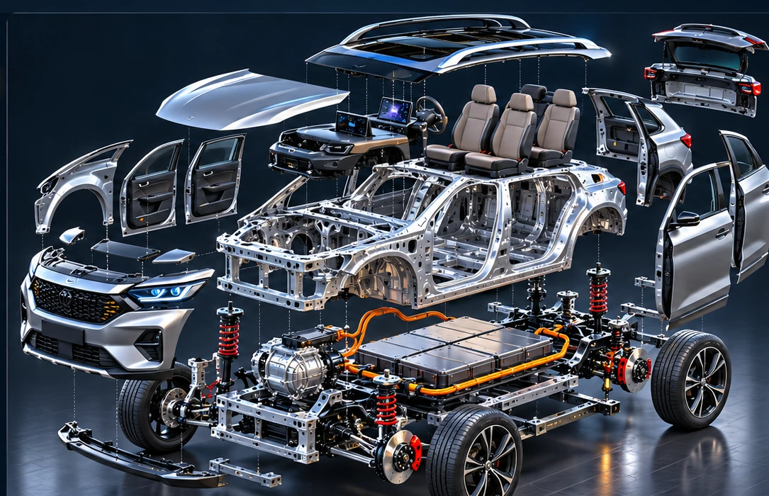
A refined interactive 3D concept of PRATIXUS3, a modern five-door battery-electric SUV. Select a vehicle system to explore its architecture, function, interfaces and manufacturing considerations.
Rotate, zoom, isolate vehicle systems and explore an exploded assembly in the browser.
Navigate vehicle → system → sub-system → component, with function, material, process and interface information.
Connect validated CAD assemblies, technical drawings, BOM structures, dimensions and manufacturing constraints.
Explore realistic automotive product imagery to understand assemblies, sub-assemblies, components and interfaces; visuals are illustrative and do not reproduce confidential project drawings.
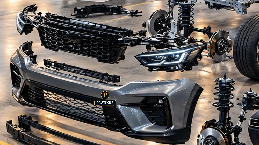
Hood, bumper, lighting, fenders and front structural interfaces.

Roof, pillars, side structure and floor architecture.
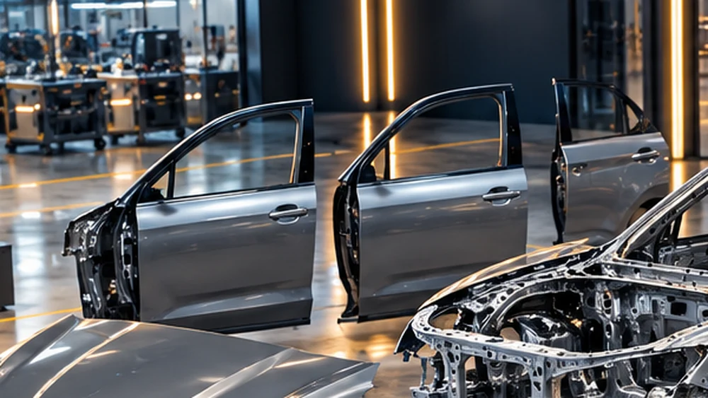
Doors, hood, tailgate, hinges, locks, seals and adjustment interfaces.
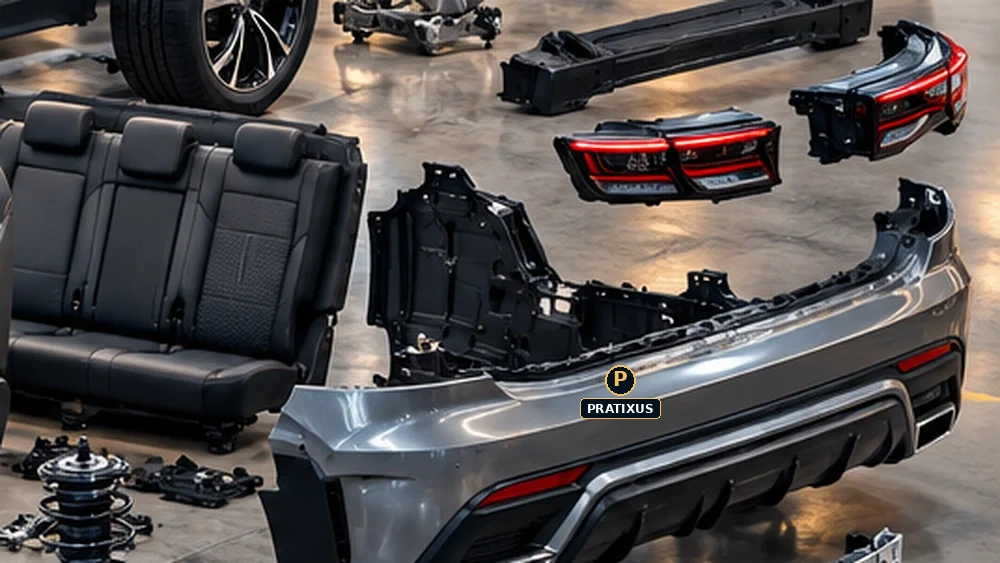
Tailgate, rear lamps, bumper, spoiler and trim interfaces.
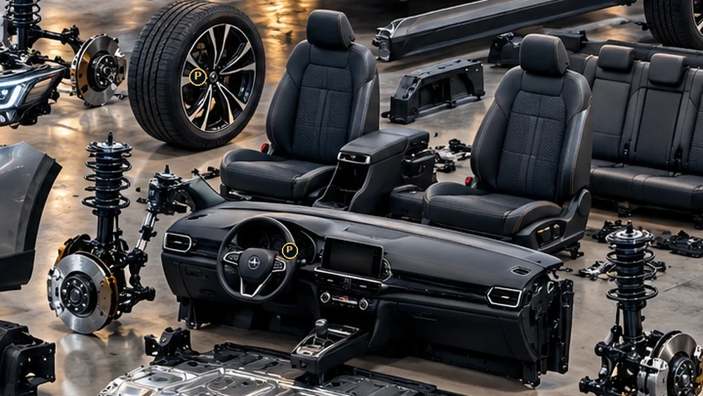
Seats, belts and representative interior/exterior equipment.
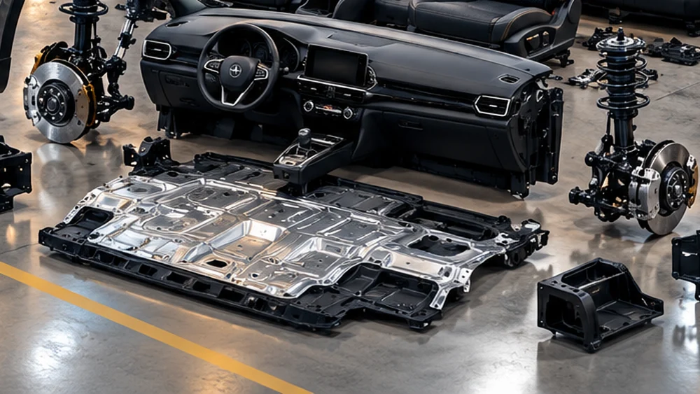
Floor, shields, tanks and interfaces for thermal, energy and exhaust systems.

Roof, glazing, roof trims, antenna and associated components.

High-level reading of assemblies, sub-assemblies and component interfaces.
Locate the assembly, sub-assembly and component. Clarify its physical and functional interfaces.
Connect the component to its product definition, configuration, supplier scope and expected deliverables.
Translate the structure into tooling, process, control, logistics, validation and assembly requirements.
When a component changes, assess interfaces, affected assemblies, validation, implementation and configuration.
When a change affects a component, assembly or interface, the supplier's QCTP response should identify exactly which product definition is changing. It should also state the quality and validation commitment, cost impact, and timing for samples, tooling, tests and implementation.
Requirements, acceptance criteria, validation plan and supplier quality commitment.
Change cost, tooling or non-recurring costs, piece-price impact and agreed assumptions.
Lead time, samples, tooling, tests, approvals and planned implementation date.
Functional, technical and vehicle-level performance requirements, targets, constraints and validation evidence affected by the change.
Practical rule: before approving a supplier modification, request a documented QCTP impact assessment and explicit commitments. QCTP is also commonly referred to as QCDP in French-speaking teams.
Continue learning
For more training on automotive product design and structural safety topics, explore:
Affiliate disclosure: PRATIXUS may earn a commission from eligible purchases through these links, at no extra cost to you.
Type a topic and press Enter.